DriveSaver Installation Instructions
 Step 1 Step 1
-
With boat in the water, loosen hardware (do not remove) connecting propeller flange and reverse gear flange sufficiently so that alignment of engine can be checked using a feeler gauge. Bolts should remain loosely connected during alignment to support the propeller flange. Align engine installation to .005” maximum by adjusting engine mounts.
-
After successful alignment, completely disconnect propeller flange from reverse gear flange supporting dead weight of propeller flange.
NOTE: Shaft may have to be cut and the keyway re-machined to compensate for the thickness of the DriveSaver®.
 Step 2 Step 2
-
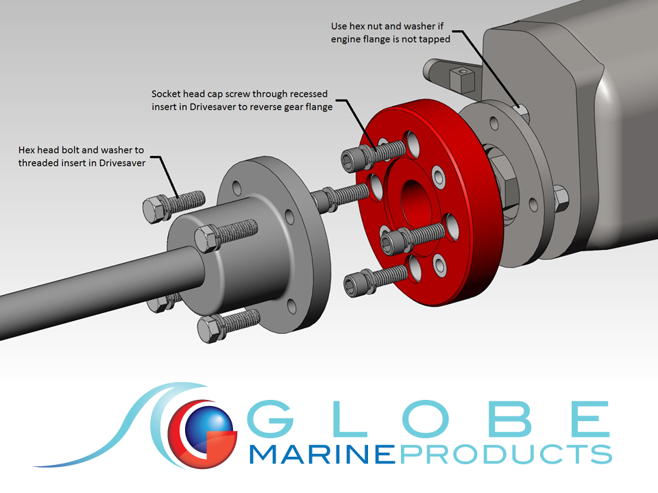
Install DriveSaver® to reverse gear flange by mating male pilot of Drivesaver® with female pilot of flange.
-
Rotate Drivesaver® to align socket head bolts with bolt holes of reverse gear flange.
-
Install socket head bolts using lock washers and nuts provided. Use small amount of waterproof grease to lubricate and protect inserts. Tighten in a “Z” pattern to torque ratings listed below.
NOTE: Some DriveSaver® models may have studs to attach to propeller flange. Install using lock washers and nuts provided, tighten in “Z” pattern to torque specifications listed below.
Step 3
-
Slide propeller shaft and flange forward to mate with female pilot of Drivesaver®. Insert hex head bolts with lock washers into threaded inserts of Drivesaver®.
-
Use small amount of waterproof grease to lubricate and protect inserts. Lightly hand-tighten in a “Z” pattern to adequately support flange.
-
Use a dial indicator on propeller shaft directly behind flange to determine runout. Tap on outside of flange or Drivesaver® to bring installation as close to .005” TIR as possible. Finish tightening in a “Z” pattern to torque ratings listed.
After Installation
-
Recheck torque and alignment of shaft after 10 to 15 hours of operation.
-
If a bond is desired, use a piece of strip copper, punched for bolt size between offsetting inserts.
-
For models requiring a bushing kit, install bushing in flange hole before mating Drivesaver® to flange.
-
Bushing may be cut to length to fit flange.
Recommended Torque Specifications
|
|
25 ft-lb
|
35 ft-lb
|
55 ft-lb
|
110 ft-lb
|
200 ft-lb
|
|
|
303*
|
504
|
5756
|
908
|
1058
|
|
|
354*
|
504AC
|
5756A
|
908A
|
1058PR
|
|
|
353
|
504H
|
5756APR
|
908AC*
|
1108
|
|
|
404
|
504HPR
|
5756AZF
|
908PR
|
1108A*
|
|
|
357*
|
504PR
|
5756PR
|
908S
|
|
|
|
404A
|
4756
|
8010Z
|
908SPR
|
|
|
|
404AC
|
4756A
|
8010ZPR
|
7256
|
|
|
|
404V
|
4756APR
|
|
7256PR
|
|
|
|
404S*
|
4756PR
|
|
7258ZPR
|
|
|
|
424*
|
6256*
|
|
7306Z
|
|
|
|
424Y
|
6256PR
|
|
8078Z
|
|
|
|
454
|
|
|
|
|
|
|
504A
|
|
|
|
|
|
|
504APR
|
|
|
|
|
|
|
524Y
|
|
|
|
|
|
|
554
|
|
|
|
|
|
|
554PR
|
|
|
|
|
* Discontinued
|
